Description
Specifications
| Analog Inputs | ||||||||||||||||||||||||||||
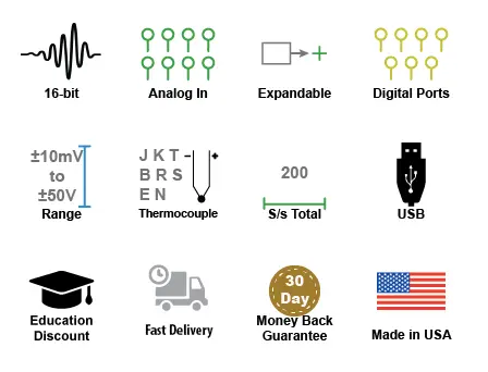
| Number of Channels: | 8 | |||||||||||||||||||||||||||
| Configuration: | Differential, Isolated | |||||||||||||||||||||||||||
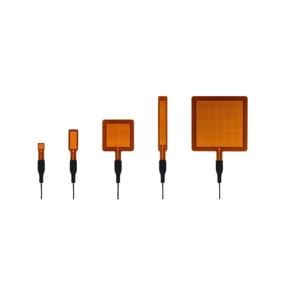
| Programmable measurements per channel: | Voltage, Thermocouple | |||||||||||||||||||||||||||
| Programmable thermocouple types and measurement range per channel:
Over 25 ±5 °C ambient temperature range. |
To increase the accuracy of thermocouple reading, please follow this steps
|
|||||||||||||||||||||||||||
| Programmable voltage measurement ranges per channel: | ±10 mV, ±25 mV, ±50 mV, ±100 mV, ±250 mV, ±500 mV, ±1 V, ±2.5 V, ±5 V, ±10 V, ±25 V, ±50 V | |||||||||||||||||||||||||||
| Voltage measurement accuracy: At 25 °C ambient temperature. Following 30 minutes warm-up. Excluding common mode error. |
±(0.05% of range + 10 µV) | |||||||||||||||||||||||||||
| Input impedance: | 1 MΩ, all ranges | |||||||||||||||||||||||||||
| Isolation: | 350Vpp, Input-to-output, Channel-to-channel | |||||||||||||||||||||||||||
| Absolute maximum input without damage: | 120 V rms | |||||||||||||||||||||||||||
| Maximum common mode voltage: | 120 V rms | |||||||||||||||||||||||||||
| Min common mode rejection (330Ω unbalance): | >100 dB (DC to 60 Hz) | |||||||||||||||||||||||||||
| Channel-to-channel crosstalk rejection: (Rsource ≤ 330 Ω; Freqsource ≤ 60 Hz) | > 100 dB at any throughput | |||||||||||||||||||||||||||
| Digital Inputs | ||||||||||||||||||||||||||||
| Number of ports: | 7 | |||||||||||||||||||||||||||
| Type: | MOSFET switch | |||||||||||||||||||||||||||
| Configuration: | Programmable as an input or switch | |||||||||||||||||||||||||||
| Pull-up value: | 4.7 KΩ | |||||||||||||||||||||||||||
| Isolation: | None | |||||||||||||||||||||||||||
| Input high voltage threshold: | 2.4 V minimum | |||||||||||||||||||||||||||
| Input low voltage threshold: | 0.8 V maximum | |||||||||||||||||||||||||||
| Absolute max input without damage: | 0 ≤ V ≤ 30 V | |||||||||||||||||||||||||||
| Count/Rate | ||||||||||||||||||||||||||||
| Digital port assignment: | Count: Port 2 configured as input Rate: Port 3 configured as input |
|||||||||||||||||||||||||||
| Internal pull-up value: | 4.7 kΩ | |||||||||||||||||||||||||||
| Input high voltage threshold: | 2.4 V | |||||||||||||||||||||||||||
| Input low voltage threshold: | 0.8 V | |||||||||||||||||||||||||||
| Terminal count: | 65,535 | |||||||||||||||||||||||||||
| Maximum rate frequency: | 50 kHz | |||||||||||||||||||||||||||
| Minimum rate frequency: | 0.5 Hz | |||||||||||||||||||||||||||
| Maximum count frequency: | 50 kHz | |||||||||||||||||||||||||||
| Power | ||||||||||||||||||||||||||||
| Power Consumption: | 0.75 Watts (from USB port) | |||||||||||||||||||||||||||
| Excitation output: | +15 V dc (-7.5% to +2.5%) at 70% load (47 mA), 67 mA at full load, or max three 4-20mA sensors | |||||||||||||||||||||||||||
| ADC Characteristics | ||||||||||||||||||||||||||||
| Voltage Measurement Resolution: |
|
|||||||||||||||||||||||||||
| Thermocouple Temperature Measurement Resolution: |
|
|||||||||||||||||||||||||||
| 4-20 mA current loop resolution: | 13,100 ADC counts over the 4-20 mA range (5 VFS range with 250-Ω shunt resistor) | |||||||||||||||||||||||||||
| Maximum sample throughput rate: | Single enabled channel: 2,000 S/s Two or more enabled channels: 200 S/s |
|||||||||||||||||||||||||||
| Minimum sample throughput (hardware): | 1 enabled analog channel: 0.000109 S/s 2 or more enabled analog channels: 0.000011 S/s |
|||||||||||||||||||||||||||
| Minimum sample throughput (using WinDaq): | .0001969 S/s | |||||||||||||||||||||||||||
| Sample rate timing accuracy: | 50 ppm | |||||||||||||||||||||||||||
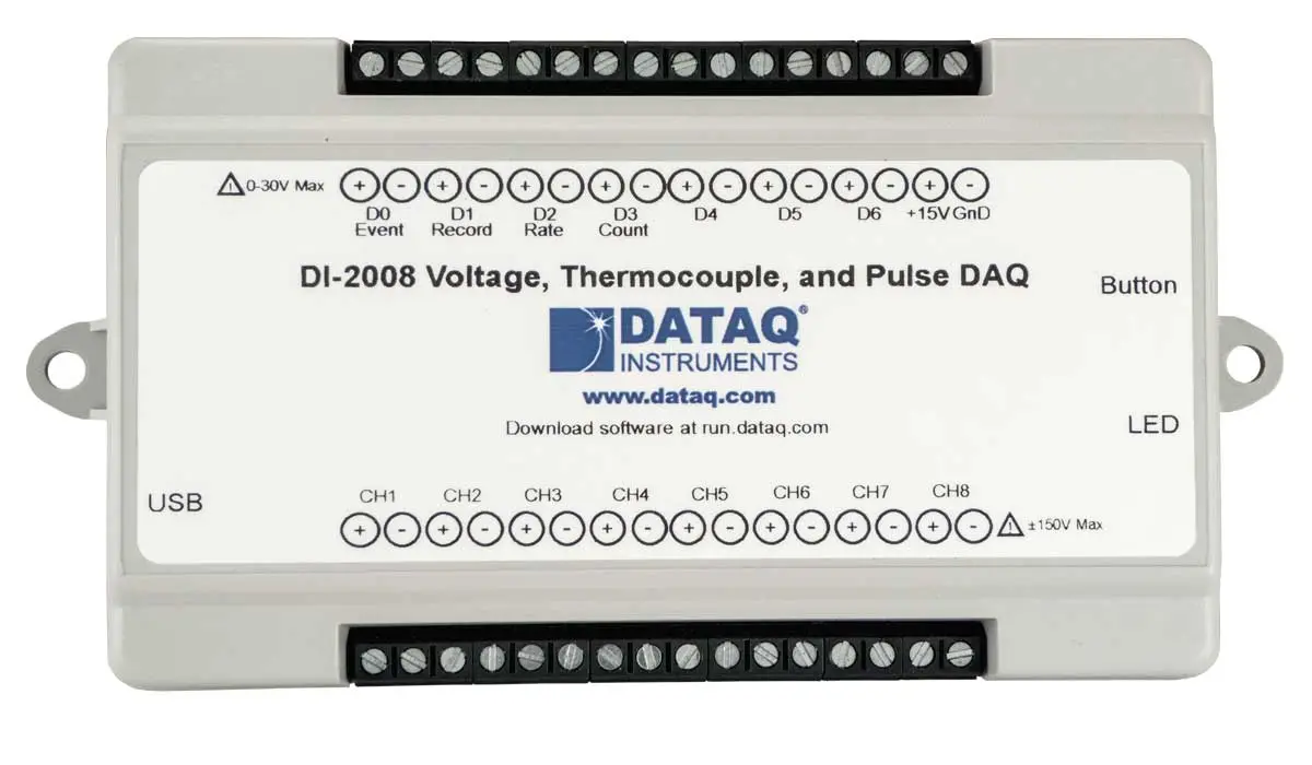
| Indicators and Connections | ||||||||||||||||||||||||||||
| Interface: | USB 2.0 (mini-B style connector) | |||||||||||||||||||||||||||
| Indicator lights: | 3 LEDs: Power, Active, Event | |||||||||||||||||||||||||||
| Input Connections: | Two 16-position terminal strips | |||||||||||||||||||||||||||
| Pushbutton: | Manual event when used with WinDaq software | |||||||||||||||||||||||||||
| ChannelStretch™ Operation | ||||||||||||||||||||||||||||
| WinDaq software: | If any synced device has two or more enabled analog channels, all synced devices must enable the same number of analog and digital channels and the same sample throughput rate. If all synced devices have one or zero enabled analog channels, sample rate per channel must be the same across all devices. One or more digital ports configured as a discrete input counts as one digital channel. Rate and count inputs count as one digital channel each. | |||||||||||||||||||||||||||
| Programmed (.Net- or protocol-based): | Sample rate per channel must be the same across all synced devices. | |||||||||||||||||||||||||||
| Maximum number of devices: | 16 | |||||||||||||||||||||||||||
| Maximum channel count: | 128 analog, 112 digital | |||||||||||||||||||||||||||
| Maximum supported throughput: | ≥480 kHz | |||||||||||||||||||||||||||
| Synchronization compatibility: | DI-2008 | |||||||||||||||||||||||||||
| PC USB prerequisite: | All instruments must be connected to the same USB controller. The use of USB hubs are recommended to meet this requirement. | |||||||||||||||||||||||||||
| Environmental | ||||||||||||||||||||||||||||
| Operating Temperature: | 0 to 70 °C | |||||||||||||||||||||||||||
| Storage Temperature: | -20 to 70 °C | |||||||||||||||||||||||||||
| Storage Humidity: | 0 to 90% non-condensing | |||||||||||||||||||||||||||
| Physical Characteristics | ||||||||||||||||||||||||||||
| Enclosure: | Hardened Plastic | |||||||||||||||||||||||||||
| Mounting: | Desktop; bulkhead | |||||||||||||||||||||||||||
| Dimensions: | 3.28D × 6.68W × 1.13H in. (83.31D × 169.67W × 28.7H mm.) | |||||||||||||||||||||||||||
| 3D Model | Click here | |||||||||||||||||||||||||||
| Weight: | 5.7 oz. (162 grams) | |||||||||||||||||||||||||||