Description
Building thermal resistance measuring system
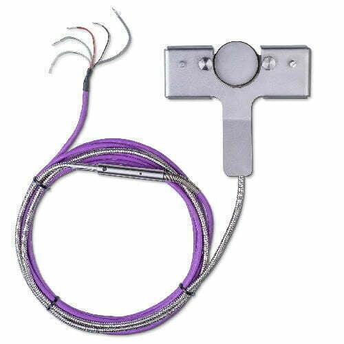
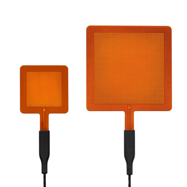
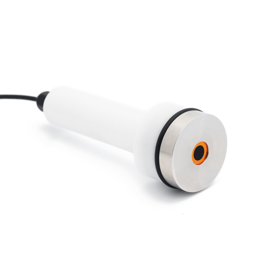
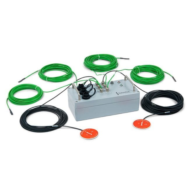
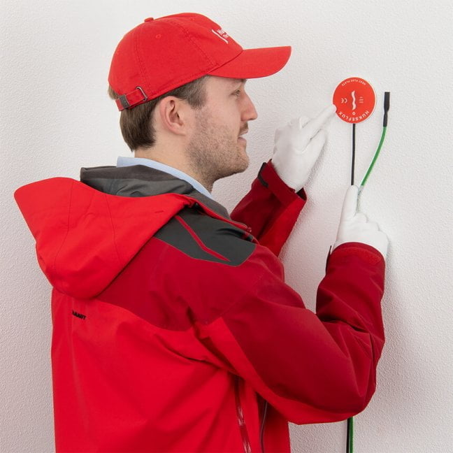
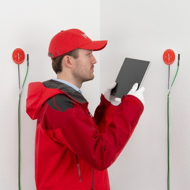
The high-sensitivity HFP01 heat flux sensors combined with the robust, high-resolution electronics ensure that TRSYS20 continues making meaningful measurements when other systems no longer perform; in particular at very low heat fluxes and low temperature differences across the wall. The matched thermocouple pairs allow measurement of temperature differences with an uncertainty better than 0.1 °C over the entire temperature range. Two measurement locations provide redundancy allowing the user to verify that the measurement results are representative for the building envelope component.

User interface: MCU as a web server
TRSYS20 is controlled via a PC. No software installation is required. The measurement and control unit (MCU) can be connected to a local area network (LAN) via ethernet or directly to a PC via USB. The MCU provides a graphical user interface in the form of a webpage that is accessible through a web browser. The graphical user interface allows the user to start and stop experiments; to monitor real-time heat flux, temperature and temperature difference measurement data; and to review preliminary results.
The system generates a data file, containing the measurement time, heat flux, temperature and temperature difference for the two measurement locations. The data file is stored in the MCU and can be downloaded through the graphical user interface. The user is responsible for the data analysis, calculating the R-, Λ- or U-value of the building envelope according to the ISO 9869 or ASTM C1155 standards.
Unique features and benefits
- robust and stable
- best paperwork: complies with ISO and ASTM standards
- temperature difference sensors: tested for 0.1 °C accuracy requirements
- simultaneous measurements on two locations
- measures very small heat fluxes
- intuitive and easy to use graphical user interface
- connection via ethernet (LAN) or USB
- water- (rated IP67) and corrosion proof sensors
Calibration & conformity assessment
Calibration of TRSYS20 components is traceable to international standards. TRSYS20 is provided with formally traceable calibration certificates. HFP01 heat flux sensors are calibrated in accordance with ASTM C1130. Temperature difference sensors are “individually” tested as matched pairs.
Specifications
| Measurand | heat flux (2 x), temperature (4 x), temperature difference (2 x) |
|---|---|
| TRSYS20 specifications | : |
| Uncertainty of calibration |
±3 % (k = 2) |
| Measurement resolution |
0.02 W/m² |
| Guard width to thickness ratio |
5 m/m (as required by ISO 9869 D.3.1) |
| Accuracy |
< ± 0.1 °C (as required by ISO 9869, paragraph 5.2) |
| Measurement resolution |
0.02 °C |
| Thermocouple type |
IEC 60584-3:2007 type KX |
| Tolerance class |
Class II |
| Required data analysis to determine building R-value and U-value |
to be performed by the user according to ISO and ASTM standard practices |
| Standards governing use |
ISO 9869, ASTM C1046, ASTM C1155 |
| Number of measurement locations |
2 |
| Cable length per location |
location 1: 10 m, location 2: 20 m |
| Rated operating temperature range HFP01 and TC |
-30 to +70 °C |
| Measurement duration range |
> 3 days |
| Data storage capacity |
> 30 days |
| MCU specifications |
: |
| Connection |
to local area network (LAN) via ethernet or directly to PC via USB |
| Graphical user interface |
web page via web browser |
| Supported web browsers |
Chrome 10, Firefox 4, Internet Explorer 9, Opera 11, Safari 5, or later |
| Rated operating voltage MCU |
10 to 16 VDC |
| Ingress protection class |
IP54 |
| PSU specifications |
: |
| Input voltage |
110-220 VAC, 50 / 60 Hz |
| Ingress protection class |
IP22 |
Suggested Use
- Heat flux and differential temperature measurement for building R-value, Λ-value or U-value determination
Frequently asked questions
How to measure heat flux?
Heat flux sensors measure energy flux onto or through a surface in [W/m²].
The source of the heat flux may be:
- conduction
- radiation
- convection
Convective and conductive heat transfer are associated with a temperature difference. Heat always flows from a source to a sink, from a hot to a cold environment. Convective and conductive heat flux is measured by letting this heat flow through the sensor. Radiative flux is measured using heat flux sensors with black absorbers. The absorbers converts radiative to conductive energy. Hukseflux started in 1993 with sensors for measurement of heat flux in soils and on walls. In the course of the years, we have added specialised sensors and systems for many other applications.
Heat flux sensors manufactured by Hukseflux are optimised for the demands of different applications:
- rated temperature range
- rated heat flux range
- sensitivity
- response time
- chemical resistance, safety requirements
- size, shape and spectral properties
Hukseflux is the world market leader in heat flux measurement. If you do not understand what heat flux is please refer to our informational article on heat flux.
What is a heat flux sensor?
To learn more about what a heat flux sensor is, check out our page called What is a Heat Flux Sensor?
What matters most when measuring with a heat flux sensor?
There are quite a few general considerations when starting a heat flux measurement.
- Representativeness in time and space; average!
A heat flux sensor measures at a certain location. Is this location representative of what you need to measure? If possible, use a relatively large sensor, rather than a small one, and consider use of multiple sensors. Thermal processes often have large time constants; instantaneous measurements may be misleading. Average to get the full picture. - Optical properties
When heat flux sensors also measure radiation, pay attention to the surface color. If needed paint the sensor surface. Please mind that shiny metallic surfaces reflect both infra-red and visible radiation. Paints may have different colors in the visible range, but are usually “black” absorbers in the far-infra-red. - Sensor thermal resistance
A heat flux sensor distorts the local heat flux. In order to minimize this effect, use the sensor with the lowest possible thermal resistance. - Edge effects
A heat flux sensor locally distorts the heat flow pattern, in particular around the edges of the sensor. A passive guard, i.e. a non-sensitive part around the sensor is essential to avoid errors due to edge effects.
There are more characteristics that matter. Please find them in our white paper on heat flux fundamentals and applications.
Which sensor(s) to use for surface energy flux measurement?
Hukseflux manufactures a range of sensors for surface energy flux measurements. All have proven reliability.
These state-of-the-art sensors are made for the global fluxnet community:
- NR01 is a market leading 4-component net radiometer.
- HFP01 and HFP01SC measure soil heat flux.
- STP01 offers an accurate temperature profile measurement.
- TP01 is the leading sensor for soil thermal conductivity.
Sensors made by Hukseflux are designed for compatibility with most common datalogger models. For many models we have example programs and wiring diagrams available.
How to measure R-value and U-value of buildings?
On-site measurements of thermal resistance, R, are often applied in studies of buildings. Alternatives are to measure its inverse value, the thermal conductance which is called the Λ-value, or the thermal transmittance which includes ambient air boundary layer thermal resistance, the U-value. The measurements of R are based on simultaneous time averaged measurement of heat flux Φ and differential temperature, ΔT, (using two temperature sensors on each on a different side of the wall).
R = ΔT / Φ
Hukseflux provides a range of sensors and measuring systems for use in measurement of the energy budget of buildings and characterization of construction materials.
HFP01 heat flux sensor and TRSYS01 measuring system are widely used for on-site measurements on walls, windows and other construction elements in building physics.
- HFP01 can be used for in-situ measurement of building envelope thermal resistance (R-value) and thermal transmittance (H-value) according to ISO 9869, ASTM C1046 and ASTM 1155 standards. HFP01 is the world’s most popular sensor for heat flux measurement in the soil as well as through walls and building envelopes. HFP01 measures heat flux through the object in which it is incorporated or on which it is mounted, in W/m². More information? Visit the HFP01 product page.
- TRSYS01 is a high-accuracy system for on-site measurement of thermal resistance, R, thermal conductance, the Λ-value, and thermal transmittance, the U-value, of building envelopes. TRSYS01 is mostly used for measurements according to standard practices of ISO 9869 and ASTM C1155 / C1046. The system is equipped with high-accuracy electronics, two heat flux sensors of model HFP01 as well as two pairs of matched thermocouples. The two measurement locations provide redundancy, leading to a high level of confidence in the measurement result. The high accuracy of the heat flux sensors and temperature difference measurements ensures that TRSYS01 continues measuring when other systems no longer perform; in particular at very low temperature differences across the wall.
Where can I find complete heat flux measuring systems?
Hukseflux, market leader in heat flux measurement, offers both sensors and systems.
These measuring systems typically include a Measurement and Control Unit and one or more sensors for measuring heat flux as well as other measurands, such as temperature and humidity. Examples are the TCOMSYS01 Hot Cube thermal comfort measuring system, including a TCOM01 sensor, and the TRSYS01 measuring system, incorporating two HFP01 heat flux sensors and two pairs of matched thermocouples.
Cannot find what you are looking for? Please contact us.